This article will demonstrate how to test a Linear Potentiometer sensor.
To watch the corresponding video, please visit this page.
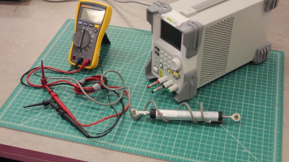
To perform this task, you will need the following tools and materials:
- A DC power supply
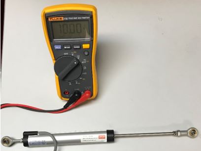
- A DC volt meter
- A Linear Potentiometer
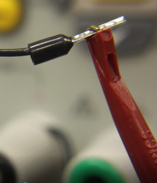
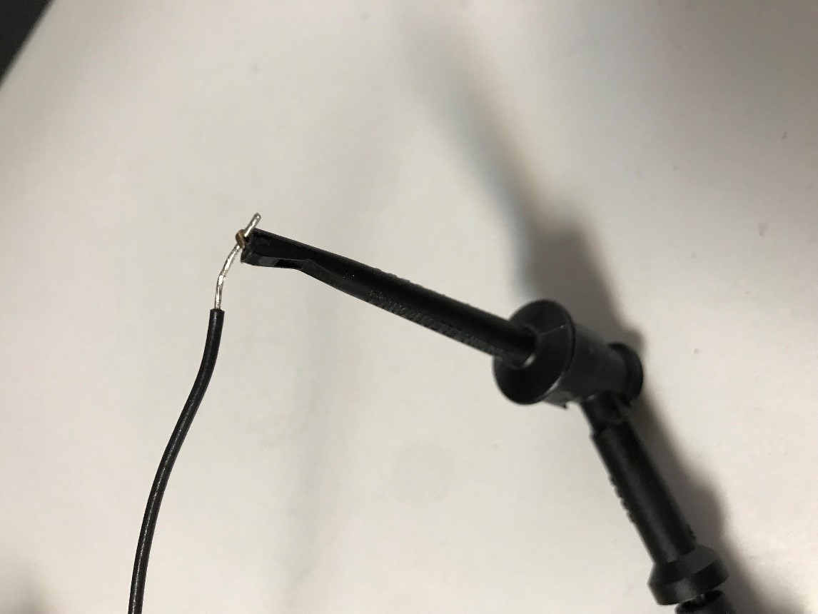
- A 4 inch long insulated copper jumper wire, stripped a 1/4 of an inch both ends
A 3 wire Linear Potentiometer circuit is a variable voltage divider; as the wiper moves along the resistive element, it provides an output voltage proportional to displacement. The full-scale output voltage is equivalent to the excitation voltage. For example, an excitation voltage of 10 Volts DC would produce an output of 0 to 10 Volts DC.
Begin by attaching the jumper wire to the negative terminal of the power supply
Next, attach the sensor’s positive excitation wire to the positive terminal of the power supply.
Then attach the sensor’s negative excitation wire to the negative terminal of the power supply.
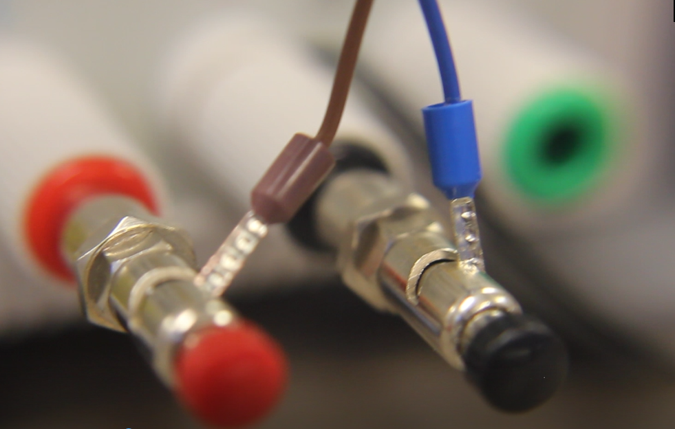
Connect the positive lead of the DC volt meter to the sensor’s signal output wire.
Connect the negative lead of the DC volt meter to the jumper wire that is attached to the negative terminal of the power supply.
Set the volt meter to measure DC voltage.
Set the DC power supply to 10 volts DC.
With the Linear Potentiometer fully retracted, the Volt Meter should display 0 Volts DC.
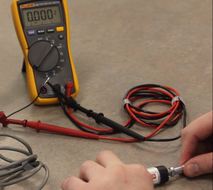
With the Linear Potentiometer fully extended, the Volt Meter should display 10 Volts DC.